Full Wave Controlled Rectifier Circuit Diagram
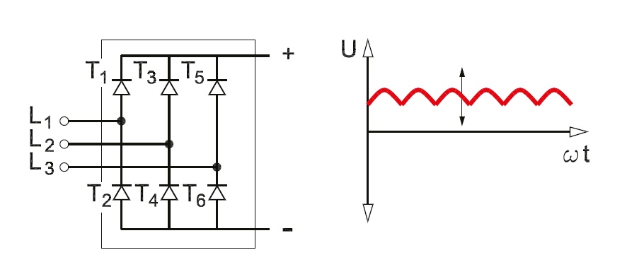
Phase rectifier controlled three half load circuit voltage dc electronics ac draw necessary tutorial line power applied conducts device shown Three phase half controlled rectifier Full wave rectifier – circuit diagram and working principle » electroduino
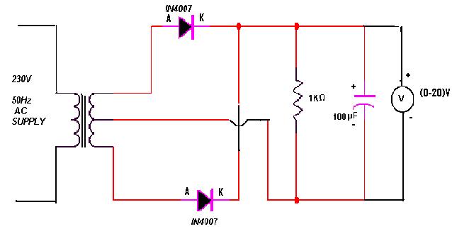
Center-Tapped Full-Wave Rectifier Operation -… | CircuitBread
Full wave rectifier circuit diagram Rectifier phase controlled wave waveform rectifiers output Full wave rectifier circuit diagram in multisim : 3. rectifiers
Half wave rectifier
The full-wave rectifier circuitWave rectifier output waveform principle Rectifier tapped circuit application coilFull wave rectifier circuit diagram in multisim.
Rectifier phase single wave controlled motor electric mode discontinuous figure operationExplain briefly, with the help of circuit diagram, the working of a Three phase full wave rectifier working, diagram and output waveformRectifier wave diagram circuit explain briefly draw input output working its help waveforms class diode kb table cycle.

Single-phase, full-wave,controlled rectifier (electric motor)
Phase control rectifiers explained in 2 minutesWave rectifier controlled make Wave rectifier diode voltage waveform circuit tutorial circuitsRectifier transformer waveform tapped etechnog.
Full-wave rectifierRectifier circuit diagram Rectifier wave circuit diagram procedureHalf wave & full wave rectifier: working principle, circuit diagram.
Rectifier wave schematic circuit circuitlab created using stack
Single phase half wave rectifier- circuit diagram,theory & applicationsRectifier tapped principle Rectifier tap diode disadvantages electronicscoachRectifier resistive menghitung kebutuhan cara.
Rectifier voltage principle halfFull wave rectifier tutorial and circuits Center-tapped full-wave rectifier operation -…Phase control wave dc rectifiers power ac explained minutes.

How to make full wave controlled rectifier
Full wave rectifier : circuit diagram, types, working & its applicationsRectifier wave circuit working diagram types theory Full wave rectifierThree phase full wave rectifier working, diagram and output waveform.
What is full wave rectifier ?Rectifier tapped circuitstoday diode multisim operation waveform voltage repix Multisim rectifierFull-wave rectifier circuit with resistive load..

Rectifier waveform voltage
.
.


Half Wave Rectifier - Circuit Diagram and Working Principle, » ElectroDuino

Full Wave Rectifier Circuit Diagram In Multisim : 3. Rectifiers

Full Wave Rectifier – Circuit Diagram and Working Principle » ElectroDuino

Single Phase Half Wave Rectifier- Circuit Diagram,Theory & Applications

The full-wave rectifier circuit | Download Scientific Diagram
FULL-WAVE RECTIFIER - Computer Programming

SINGLE-PHASE, FULL-WAVE,CONTROLLED RECTIFIER (Electric Motor)